Maximize Your Equipment’s Performance with Cotta Speed Reducers
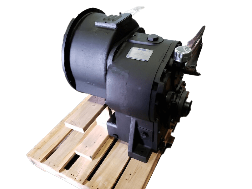
For over 100 years Cotta has been making American made high performance speed reducers. Our long history of precision engineered gearboxes is reflected in the durability and reliability of our speed reducers, which are designed to get the most out of your heavy-duty industrial equipment through the use of gear trains.
Speed Reducer in a Nutshell
A speed reducer, also known as a gear reducer or gearbox speed reducer, minimizes the speed of a motor or engine while simultaneously increasing its output torque. This is achieved through a gear train, which transmits power from the input shaft to the output shaft.
Speed reducers are vital components in equipment operation, enabling motors to function at optimal speeds while delivering the necessary torque for various applications. They help enhance efficiency, lifespan of the motor, as well as minimizing energy consumption.
Worm gear reducers are popular in various industries due to their compact design and low maintenance. They use a worm gear and worm wheel to achieve high gear ratios, delivering high torque at low speeds. They come in various sizes and configurations, offering speed reduction ratios like 10:1, 15:1, 20:1, 30:1, 40:1, or 50:1. The output shaft can be hollow or solid and may feature left or right-hand threading. Some models of a worm gear reducer also offer double-projecting output shafts for added installation flexibility.
Designed for Maximum Efficiency
Cotta Speed Reducers match the engine speed to the optimal driven equipment speed so both can run at peak efficiency.
Cotta’s gearboxes and gear motors are used in many demanding applications, including masthead drills, and ancillary machinery. Reducing motor speed is crucial in various industrial applications, and Cotta speed reducers and even speed increasers achieve this by lowering the rotational speed of motors while increasing output torque.
Whether diesel engines, electric motors or PTO’s Cotta speed reducers get the job done in the toughest environments.
Custom Solutions for Your Application
We also know that every application is different. That’s why we offer custom-engineered speed reducers to fit your specific needs. Cotta custom speed reducers are designed to optimize output torque for various applications.
Cotta works with your team to gather critical information such as input speed, output speed, flywheel housing size, and direction of rotation to recommend the best solution. Calculating the reduction ratio is crucial to ensure the desired output rotational speed and optimal performance for your specific application. We have expertise in custom speed reducers for high RPM applications so your equipment can perform at its best regardless of industry. Cotta has expertise in custom speed reducers that efficiently transfer power from the motor shaft to the output shaft.
Cotta Gear Reducers Features
- High Performance in Demanding Applications – Cotta speed reducers are built to withstand the tough demands of industries like drilling, oil & gas, and construction.
- Custom Engineering – If one of our standard units doesn’t fit your needs our engineering team can design a custom solution for you.
- Durable and Reliable – Heavy duty design with tapered roller bearings for high RPM capabilities to last in many industrial applications.
- Efficient Gear Train Configurations – Cotta speed reducers utilize efficient gear train configurations to enhance performance.
Gear Reducer Installation and Maintenance
Cotta speed reducers require rear support and are clockwise when facing the input shaft. Some Cotta speed reducers operate at a right angle to the motor shaft, providing space-saving benefits. To get the most out of your gearbox and longest life, you must lubricate the gearbox with gear oil before use and follow recommended maintenance procedures to ensure the longevity of the output shaft and overall gearbox.
Testing and Gear Reducer Quality Assurance
All Cotta speed reducers are tested at our state-of-the-art facility to meet the highest quality standards. Cotta’s testing procedures ensure optimal torque output for all speed reducers. Our test lab located in Janesville, WI has high RPM testing capabilities to give you a comprehensive look at the gearbox performance before it ships. With our zero-defect policy every product is inspected in detail to ensure reliability in the toughest applications.
Why Cotta?
Over 100 years of gearbox experience Cotta is the industry leader. Our speed reducers are lifetime warranted and engineered to last. When you choose Cotta, you get a custom solution for your industry.
Popular Speed Reducers:
Some of our most popular speed reducers are shown below, and listed on this Tabulation Chart, but please contact Cotta for your specific needs.


AR2053A
Specifications
- OUTPUT ROTATION: Opposite input
- MAX INPUT TORQUE: 500 lb-ft.
- MAX INPUT SPEED: 3000 rpm or as otherwise limited by input coupling or clutch.
- RATIOS: 1.0 to 3.0 std. 3.94 by special order
- OUTPUT SHAFT SIZE: 2.25” dia., X 5” long. 5/8” X 5/16” keyway
- OUTPUT SHAFT LOCATION: 6 o’clock std, 12, 3, and 9 o’clock optional
- SAE HOUSINGS: #2, #3, #4
- *FLYWHEEL COUPLINGS: Clutches, couplings, and drive plates up to SAE 11”.
- REAR SUPPORT: Required. Customer supplied item. Mounting holes provided per dwg.
- LUBRICATION: Splash standard, pump optional.
- COOLING: Oil/water shell-and-tube cooler furnished if required. Various options.
- **SIDE LOAD CAPABLE: No. Contact Cotta for recommendations.
- ***APPROXIMATE WEIGHT: 400 lbs.
* Flywheel coupling selection requires Cotta technical review and approval.
** Some speed reducers output shafts are suitable for chain or belt side pull drives while others are not. Provide complete application details to Cotta for recommendations and approval.
*** Weight listed is an average. Actual weight can vary substantially with options such as SAE housing size and flywheel coupling choices.
AR2053E
Specifications
- OUTPUT ROTATION: Same as input
- MAX INPUT TORQUE: 350 lb-ft.
- MAX INPUT SPEED: 3000 rpm unless otherwise limited by input clutch or coupling.
- RATIOS: 1.16 to 3.71. 4.0 by special order
- OUTPUT SHAFT SIZE: 2.25” dia., X 5” long. 5/8” X 5/16” keyway
- OUTPUT SHAFT LOCATION: 6 o’clock std, 12, 3, and 9 o’clock optional
- SAE HOUSINGS: #2, #3, #4
- *FLYWHEEL COUPLINGS: Various clutches and couplings through SAE 11”.
- REAR SUPPORT: Required. Customer supplied item. Mounting holes provided per dwg.
- LUBRICATION: Splash standard, pump optional.
- COOLING: Oil/water shell-and-tube cooler furnished if required. Various options.
- **SIDE LOAD CAPABLE: No. Contact Cotta for recommendations.
- ***APPROXIMATE WEIGHT: 415 lbs.
* Flywheel coupling selection requires Cotta technical review and approval.
** Some speed reducers output shafts are suitable for chain or belt side pull drives while others are not. Provide complete application details to Cotta for recommendations and approval.
*** Weight listed is an average. Actual weight can vary substantially with options such as SAE housing size and flywheel coupling choices.


GR15A
Specifications
- OUTPUT ROTATION: Opposite to input.
- MAX INPUT TORQUE: 1450 lb-ft.
- MAX INPUT SPEED: 2350 RPM or as otherwise limited by input clutch or coupling.
- RATIO RANGE: 1.08 TO 2.46
- OUTPUT SHAFT SIZE: 4” dia., 9” long, 1” x 1/2” keyway
- OUTPUT SHAFT LOCATION: 6 o’clock std, 12, 3, and 9 o’clock optional.
- SAE HOUSINGS: #00, #0, #1
- *FLYWHEEL COUPLINGS: Various clutches, couplings, and drive plates through SAE 24”.
- REAR SUPPORT: Integral foot mounts provided.
- LUBRICATION: Integral Lube pump supplied.
- COOLING: Oil/water shell-and-tube cooler furnished if required. Various options.
- **SIDE LOAD CAPABLE: Yes. Contact Cotta for specs and limits.
- ***APPROXIMATE WEIGHT: 1200 lbs.
* Flywheel coupling selection requires Cotta technical review and approval.
** Some speed reducers output shafts are suitable for chain or belt side pull drives while others are not. Provide complete application details to Cotta for recommendations and approval.
*** Weight listed is an average. Actual weight can vary substantially with options such as SAE housing size and flywheel coupling choices.


GR15E
Specifications
- OUTPUT ROTATION: Same as input
- MAX INPUT TORQUE: 1450 lb-ft.
- MAX INPUT SPEED: 2300 rpm or as otherwise limited by input coupling or clutch
- RATIO RANGE: 1.28 to 2.43
- OUTPUT SHAFT SIZE: 4” dia., 9” long, 1” X 1/2” keyway
- OUTPUT SHAFT LOCATION: 6”o’clock std., 12, 3, and 9 o’clock by special design
- SAE HOUSINGS: #00, #0, #1/2, #1
- *FLYWHEEL COUPLINGS: Clutches, couplings, and drive plates up to SAE 24”.
- REAR SUPPORT: Integral foot mounts provided.
- LUBRICATION: Integral lube pump supplied.
- COOLING: Oil\water shell-and-tube cooler furnished if required. Various options.
- **SIDE LOAD CAPABLE: Yes. Contact Cotta for specs and limits.
- ***APPROXIMATE WEIGHT: 1330 lbs
* Flywheel coupling selection requires Cotta technical review and approval.
** Some speed reducers output shafts are suitable for chain or belt side pull drives while others are not. Provide complete application details to Cotta for recommendations and approval.
*** Weight listed is an average. Actual weight can vary substantially with options such as SAE housing size and flywheel coupling choices.


GR16A
Specifications
- OUTPUT ROTATION: Opposite to input.
- MAX INPUT TORQUE: 1650 lb-ft.
- MAX INPUT SPEED: 2200 RPM or as otherwise limited by input clutch or coupling.
- RATIO RANGE: 1.50 to 3.0
- OUTPUT SHAFT SIZE: 4.000” dia., 9” long, 1” X 1/2” keyway.
- OUTPUT SHAFT LOCATION: 6 o’clock std, 12, 3, and 9 o’clock optional
- SAE HOUSINGS: #00, #0, #1/2, #1
- *FLYWHEEL COUPLINGS: Various clutches, couplings, and drive plates through SAE 24”.
- REAR SUPPORT: Integral foot mounts provided.
- LUBRICATION: Integral Lube pump supplied
- COOLING: Oil/water shell-and-tube cooler furnished if required. Various options.
- **SIDE LOAD CAPABLE: Yes. Contact Cotta for specs and limits.
- ***APPROXIMATE WEIGHT: 1400 lbs
* Flywheel coupling selection requires Cotta technical review and approval.
** Some speed reducers output shafts are suitable for chain or belt side pull drives while others are not. Provide complete application details to Cotta for recommendations and approval.
*** Weight listed is an average. Actual weight can vary substantially with options such as SAE housing size and flywheel coupling choices.


GR16E
Specifications
- OUTPUT ROTATION: Opposite to input.
- MAX INPUT TORQUE: 1650 lb-ft.
- MAX INPUT SPEED: 2200 RPM or as otherwise limited by input clutch or coupling.
- RATIO RANGE: 1.50 to 3.0
- OUTPUT SHAFT SIZE: 4.000” dia., 9” long, 1” X 1/2” keyway.
- OUTPUT SHAFT LOCATION: 6 o’clock std, 12, 3, and 9 o’clock optional
- SAE HOUSINGS: #00, #0, #1/2, #1
- *FLYWHEEL COUPLINGS: Various clutches, couplings, and drive plates through SAE 24”.
- REAR SUPPORT: Integral foot mounts provided.
- LUBRICATION: Integral Lube pump supplied
- COOLING: Oil/water shell-and-tube cooler furnished if required. Various options.
- **SIDE LOAD CAPABLE: Yes. Contact Cotta for specs and limits.
- ***APPROXIMATE WEIGHT: 1500 lbs
* Flywheel coupling selection requires Cotta technical review and approval.
** Some speed reducers output shafts are suitable for chain or belt side pull drives while others are not. Provide complete application details to Cotta for recommendations and approval.
*** Weight listed is an average. Actual weight can vary substantially with options such as SAE housing size and flywheel coupling choices.


GR1600A
Specifications
- OUTPUT ROTATION: Opposite to input.
- MAX INPUT TORQUE: 3000 lb-ft.
- MAX INPUT SPEED: 2200 RPM or as otherwise limited by input clutch or coupling.
- RATIO RANGE: 1.35 to 3.07
- OUTPUT SHAFT SIZE: 4.000” dia., 9” long, 1” X 1/2” keyway.
- OUTPUT SHAFT LOCATION: 6 o’clock std, 12, 3, and 9 o’clock optional
- SAE HOUSINGS: #00, #0, #1/2, #1
- *FLYWHEEL COUPLINGS: Various clutches, couplings, and drive plates through SAE 24”.
- REAR SUPPORT: Integral foot mounts provided.
- LUBRICATION: Integral Lube pump supplied
- COOLING: Oil/water shell-and-tube cooler furnished if required. Various options.
- **SIDE LOAD CAPABLE: Yes. Contact Cotta for specs and limits.
- ***APPROXIMATE WEIGHT: 1400 lbs.
* Flywheel coupling selection requires Cotta technical review and approval.
** Some speed reducers output shafts are suitable for chain or belt side pull drives while others are not. Provide complete application details to Cotta for recommendations and approval.
*** Weight listed is an average. Actual weight can vary substantially with options such as SAE housing size and flywheel coupling choices.


GR1600E
Specifications
- OUTPUT ROTATION: Same as input.
- MAX INPUT TORQUE: 2600 lb-ft.
- MAX INPUT SPEED: 2200 RPM or as otherwise limited by input clutch or coupling.
- RATIO RANGE: 1.28 to 3.0
- OUTPUT SHAFT SIZE: 4.000” dia., 9” long, 1” X 1/2” keyway.
- OUTPUT SHAFT LOCATION: 6 o’clock std, 12, 3, and 9 o’clock optional
- SAE HOUSINGS: #00, #0, #1/2, #1
- *FLYWHEEL COUPLINGS: Various clutches, couplings, and drive plates through SAE 24”.
- REAR SUPPORT: Integral foot mounts provided.
- LUBRICATION: Integral Lube pump supplied
- COOLING: Oil/water shell-and-tube cooler furnished if required. Various options.
- **SIDE LOAD CAPABLE: Yes. Contact Cotta for specs and limits.
- ***APPROXIMATE WEIGHT: 1500 lbs.
* Flywheel coupling selection requires Cotta technical review and approval.
** Some speed reducers output shafts are suitable for chain or belt side pull drives while others are not. Provide complete application details to Cotta for recommendations and approval.
*** Weight listed is an average. Actual weight can vary substantially with options such as SAE housing size and flywheel coupling choices.


GR3200A
Specifications
- OUTPUT ROTATION: Opposite to input.
- MAX INPUT TORQUE: 5500 lb-ft.
- MAX INPUT SPEED: 2200 RPM or as otherwise limited by input clutch or coupling.
- RATIO RANGE: 1.19 to 2.89
- OUTPUT SHAFT SIZE: 4.750” dia., 7” long1.25” X .4375’’ keyway.
- OUTPUT SHAFT LOCATION: 6 o’clock std, 12, 3, and 9 o’clock optional
- SAE HOUSINGS: #00, #0
- *FLYWHEEL COUPLINGS: Various clutches, couplings, and drive plates through SAE 24”
- REAR SUPPORT: Integral foot mounts provided.
- LUBRICATION: Integral Lube pump supplied
- COOLING: Oil/water shell-and-tube cooler furnished if required. Various options.
- **SIDE LOAD CAPABLE: No. Contact Cotta for recommendations.
- ***APPROXIMATE WEIGHT: 1800 lbs.
* Flywheel coupling selection requires Cotta technical review and approval.
** Some speed reducers output shafts are suitable for chain or belt side pull drives while others are not. Provide complete application details to Cotta for recommendations and approval.
*** Weight listed is an average. Actual weight can vary substantially with options such as SAE housing size and flywheel coupling choices.


GR3200E
Specifications
- OUTPUT ROTATION: Same as input.
- MAX INPUT TORQUE: 4500 lb-ft.
- MAX INPUT SPEED: RPM or as otherwise limited by input clutch or coupling.
- RATIOS: 1.20 to 3.13
- OUTPUT SHAFT SIZE: 4.750” dia., 7” long, with 1.25” X .4375” keyway.
- OUTPUT SHAFT LOCATION: 6 o’clock std, 12, 3, and 9 o’clock optional
- SAE HOUSINGS: #00, #0
- *FLYWHEEL COUPLINGS: Various clutches, couplings, and drive plates through SAE 24”.
- REAR SUPPORT: Integral foot mounts provided.
- LUBRICATION: Integral Lube pump supplied
- COOLING: Oil/water shell-and-tube cooler furnished if required. Various options.
- **SIDE LOAD CAPABLE: No. Contact Cotta for recommendations.
- ***APPROXIMATE WEIGHT: 2000 lbs.
* Flywheel coupling selection requires Cotta technical review and approval.
** Some speed reducers output shafts are suitable for chain or belt side pull drives while others are not. Provide complete application details to Cotta for recommendations and approval.
*** Weight listed is an average. Actual weight can vary substantially with options such as SAE housing size and flywheel coupling choices.


GR975200
Specifications
- OUTPUT ROTATION: Same as input.
- MAX INPUT TORQUE: 2400 lb-ft.
- MAX INPUT SPEED: 2200 RPM or as otherwise limited by input clutch or coupling.
- RATIOS: 3.49 to 6.58.
- OUTPUT SHAFT SIZE: 5.5” dia., 8” long, with 1.0” X .5” keyway.
- OUTPUT SHAFT LOCATION: 6 o’clock std, 12, 3, and 9 o’clock optional
- SAE HOUSINGS: #00, #0, #1
- *FLYWHEEL COUPLINGS: Various clutches, couplings, and drive plates through SAE 24”.
- REAR SUPPORT: Required. Customer supplied item. Mounting holes provided per drawing.
- LUBRICATION: Integral Lube pump supplied
- COOLING: Oil/water shell-and-tube furnished if required. Various options.
- **SIDE LOAD CAPABLE: No. Contact Cotta for recommendations.
- ***APPROXIMATE WEIGHT: 2300 lbs.
* Flywheel coupling selection requires Cotta technical review and approval.
** Some speed reducers output shafts are suitable for chain or belt side pull drives while others are not. Provide complete application details to Cotta for recommendations and approval.
*** Weight listed is an average. Actual weight can vary substantially with options such as SAE housing size and flywheel coupling choices.


SR2A
Specifications
- OUTPUT ROTATION: Opposite input
- MAX INPUT TORQUE: 800 lb-ft.
- MAX INPUT SPEED: 3000 rpm or as otherwise limited by input clutch or coupling
- RATIOS: 1:1 to 3:1 Others by special design
- OUTPUT SHAFT SIZE: 3” dia., 5.5”long, 3/8” X 3/4” keyway
- OUTPUT SHAFT LOCATION: 6 o’clock std., 12, 3, and 9 o’clock optional
- SAE HOUSINGS: #1, #2, #3
- *FLYWHEEL COUPLINGS: Various clutches, couplings, and drive plates through SAE 14 inch.
- REAR SUPPORT: Required, customer supplied item. Mounting holes provided per drawing.
- LUBRICATION: Integral Lube pump supplied
- COOLING: Oil/water shell-and-tube cooler furnished if required. Various options.
- **SIDE LOAD CAPABLE: No. Contact Cotta for recommendations.
- ***APPROXIMATE WEIGHT: 775 lbs
* Flywheel coupling selection requires Cotta technical review and approval.
** Some speed reducers output shafts are suitable for chain or belt side pull drives while others are not. Provide complete application details to Cotta for recommendations and approval.
*** Weight listed is an average. Actual weight can vary substantially with options such as SAE housing size and flywheel coupling choices.


SR2E
Specifications
- OUTPUT ROTATION: Same as input.
- MAX INPUT TORQUE: 600 lb-ft.
- MAX INPUT SPEED: 3000 RPM or as otherwise limited by input clutch or coupling.
- RATIOS: 1.42 TO 3.0. Others by special design.
- OUTPUT SHAFT SIZE: 3” dia., 5.5” long, 3/4” X 3/8” keyway
- OUTPUT SHAFT LOCATION: 6 o’clock std, 12, 3, and 9 o’clock optional
- SAE HOUSINGS: #1, #2, #3
- *FLYWHEEL COUPLINGS: Various clutches, couplings, and drive plates through SAE 14 inch.
- REAR SUPPORT: Required, customer supplied item. Mounting holes provided per drawing.
- LUBRICATION: Integral Lube pump supplied.
- COOLING: Oil/water shell-and-tube cooler furnished if required. Various options.
- **SIDE LOAD CAPABLE: No. Contact Cotta for recommendations.
- ***APPROXIMATE WEIGHT: 800 lbs.
* Flywheel coupling selection requires Cotta technical review and approval.
** Some speed reducers output shafts are suitable for chain or belt side pull drives while others are not. Provide complete application details to Cotta for recommendations and approval.
*** Weight listed is an average. Actual weight can vary substantially with options such as SAE housing size and flywheel coupling choices.


SR3A
Specifications
- OUTPUT ROTATION: Opposite to input.
- MAX INPUT TORQUE: 1400 lb-ft.
- MAX INPUT SPEED: 3000 RPM or as otherwise limited by input clutch or coupling.
- RATIOS: 1.02 to 3.04. Others by special design.
- OUTPUT SHAFT SIZE: 3.5” dia., 5” long, 7/8” X 7/16” keyway
- OUTPUT SHAFT LOCATION: 6 o’clock std, 12, 3, and 9 o’clock optional
- SAE HOUSINGS: #0, #1, #2
- *FLYWHEEL COUPLINGS: Various clutches, couplings, and drive plates through SAE 18 inch.
- REAR SUPPORT: Required. Customer supplied item. Mounting holes provided per drawing.
- LUBRICATION: Integral Lube pump supplied
- COOLING: Oil/water shell-and-tube cooler supplied if required. Various options.
- **SIDE LOAD CAPABLE: No. Contact Cotta for recommendations.
- ***APPROXIMATE WEIGHT: 940 lbs.
* Flywheel coupling selection requires Cotta technical review and approval.
** Some speed reducers output shafts are suitable for chain or belt side pull drives while others are not. Provide complete application details to Cotta for recommendations and approval.
*** Weight listed is an average. Actual weight can vary substantially with options such as SAE housing size and flywheel coupling choices.


SR3E
Specifications
- OUTPUT ROTATION: Same as input.
- MAX INPUT TORQUE: 900 lb-ft.
- MAX INPUT SPEED: 3000 RPM or as otherwise limited by input clutch or coupling.
- RATIOS: 1.2 to 3.0
- OUTPUT SHAFT SIZE: 3.5” dia., 5” long, 7/8” X 7/16” keyway
- OUTPUT SHAFT LOCATION: 6 o’clock std, 12, 3, and 9 o’clock optional.
- SAE HOUSINGS: #0, #1, #2
- *FLYWHEEL COUPLINGS: Various clutches, couplings, and drive plates through SAE 18”.
- REAR SUPPORT: Required. Customer supplied item. Mounting holes provided per drawing.
- LUBRICATION: Integral Lube pump supplied.
- COOLING: Oil/water shell-and-tube cooler supplied if required. Various options.
- **SIDE LOAD CAPABLE: No. Contact Cotta for recommendations.
- ***APPROXIMATE WEIGHT: 975 lbs.
* Flywheel coupling selection requires Cotta technical review and approval.
** Some speed reducers output shafts are suitable for chain or belt side pull drives while others are not. Provide complete application details to Cotta for recommendations and approval.
*** Weight listed is an average. Actual weight can vary substantially with options such as SAE housing size and flywheel coupling choices.


SR12A
Specifications
- OUTPUT ROTATION: Opposite to input.
- MAX INPUT TORQUE: 750 lb-ft.
- MAX INPUT SPEED: 2500 RPM or as otherwise limited by input clutch or coupling.
- RATIO RANGE: 1.03 to 3.87
- OUTPUT SHAFT SIZE:
3.000” dia., 5.5” long, with 3/4” X 3/8” keyway.
3.500” dia., 5.5 long, 7/8” X 7/16” keyway above 3.45 ratio. - OUTPUT SHAFT LOCATION: 6 o’clock std, 12, 3, and 9 o’clock optional
- SAE HOUSINGS: #0, #1, #2
- *FLYWHEEL COUPLINGS: Various clutches, couplings, and drive plates through SAE 18 inch.
- REAR SUPPORT: Required. Customer supplied item. Mounting holes provided per drawing.
- LUBRICATION: Splash standard, pump optional.
- COOLING: Oil/water shell-and-tube cooler furnished if required. Various options.
- **SIDE LOAD CAPABLE: No. Contact Cotta for recommendations.
- ***APPROXIMATE WEIGHT: 750 lbs.
* Flywheel coupling selection requires Cotta technical review and approval.
** Some speed reducers output shafts are suitable for chain or belt side pull drives while others are not. Provide complete application details to Cotta for recommendations and approval.
*** Weight listed is an average. Actual weight can vary substantially with options such as SAE housing size and flywheel coupling choices.


SR12E
Specifications
- OUTPUT ROTATION: Same as input.
- MAX INPUT TORQUE: 750 lb-ft.
- MAX INPUT SPEED: 2500 RPM or as otherwise limited by input clutch o coupling.
- RATIO RANGE: 1.30 to 3.92
- OUTPUT SHAFT SIZE:
3.000” dia., 5.5” long, with 3/4” X 3/8” keyway.
3.500” dia., 5.5” long, 7/8” X 7/16”keyway above 3.45 ratio. - OUTPUT SHAFT LOCATION: 6 o’clock std, 12, 3, and 9 o’clock optional
- SAE HOUSINGS: #0, #1, #2
- *FLYWHEEL COUPLINGS: Various clutches, couplings, and drive plates through SAE 18 inch.
- REAR SUPPORT: Required Customer supplied item. Mounting holes provided per drawing.
- LUBRICATION: Integral Lube pump supplied
- COOLING: Oil/water shell-and-tube furnished if required. Various options.
- **SIDE LOAD CAPABLE: No. Contact Cotta for recommendations.
- ***APPROXIMATE WEIGHT: 815 lbs.
* Flywheel coupling selection requires Cotta technical review and approval.
** Some speed reducers output shafts are suitable for chain or belt side pull drives while others are not. Provide complete application details to Cotta for recommendations and approval.
*** Weight listed is an average. Actual weight can vary substantially with options such as SAE housing size and flywheel coupling choices.


SR700A
Specifications
- OUTPUT ROTATION: Opposite to input.
- MAX INPUT TORQUE: 650 lb-ft.
- MAX INPUT SPEED: 2500 RPM or as otherwise limited by input clutch or coupling.
- RATIO RANGE: 1.5 to 2.0
- OUTPUT SHAFT SIZE: 3”dia., 5.5” long, 3/8” X 3/4” keyway.
- OUTPUT SHAFT LOCATION: 6 o’clock
- SAE HOUSINGS: #1, no optional sizes.
- *FLYWHEEL COUPLINGS: Various clutches, couplings, and drive plates through SAE 14”.
- REAR SUPPORT: Required. Customer supplied item. Mounting holes provided per drawing.
- LUBRICATION: Splash. Pump optional if required.
- COOLING: Oil/water shell-and-tube cooler furnished if required.
- **SIDE LOAD CAPABLE: Yes. Contact Cotta for specs and limits.
- ***APPROXIMATE WEIGHT: 510 lbs
* Flywheel coupling selection requires Cotta technical review and approval.
** Some speed reducers output shafts are suitable for chain or belt side pull drives while others are not. Provide complete application details to Cotta for recommendations and approval.
*** Weight listed is an average. Actual weight can vary substantially with options such as SAE housing size and flywheel coupling choices.
SR700E
Specifications
- OUTPUT ROTATION: Same as input.
- MAX INPUT TORQUE: 650 lb-ft.
- MAX INPUT SPEED: 2500 RPM or as otherwise limited by input clutch or coupling.
- RATIO RANGE: 1.43 to 1.95
- OUTPUT SHAFT SIZE: 3”dia., 5.5” long, 3/8” X 3/4” keyway.
- OUTPUT SHAFT LOCATION: 6 o’clock
- SAE HOUSINGS: #1, no optional sizes.
- *FLYWHEEL COUPLINGS: Various clutches, couplings, and drive plates through SAE 14”.
- REAR SUPPORT: Required. Customer supplied item. Mounting holes provided per drawing.
- LUBRICATION: Splash. Pump optional if required.
- COOLING: Oil/water shell-and-tube cooler furnished if required.
- **SIDE LOAD CAPABLE: Yes. Contact Cotta for specs and limits.
- ***APPROXIMATE WEIGHT: 510 lbs.
* Flywheel coupling selection requires Cotta technical review and approval.
** Some speed reducers output shafts are suitable for chain or belt side pull drives while others are not. Provide complete application details to Cotta for recommendations and approval.
*** Weight listed is an average. Actual weight can vary substantially with options such as SAE housing size and flywheel coupling choices.


SR972A
Specifications
- OUTPUT ROTATION: Opposite to input.
- MAX INPUT TORQUE: 1000 lb-ft.
- MAX INPUT SPEED: 2200 RPM or as otherwise limited by input clutch or coupling.
- RATIO RANGE: 3.49 to 6.25
- OUTPUT SHAFT SIZE: 3.500” dia., 4.5” long, 7/8” X 7/16” keyway.
- OUTPUT SHAFT LOCATION: 6 o’clock.
- SAE HOUSINGS: #0, #1
- *FLYWHEEL COUPLINGS: Various clutches, couplings, and drive plates through SAE 18”.
- REAR SUPPORT: Required. Customer supplied item. Mounting holes provided per drawing.
- LUBRICATION: Integral Lube pump supplied.
- COOLING: Oil/water shell-and-tube cooler furnished if required. Various options.
- **SIDE LOAD CAPABLE: No. Contact Cotta for recommendations.
- ***APPROXIMATE WEIGHT: 1200 lbs.
* Flywheel coupling selection requires Cotta technical review and approval.
** Some speed reducers output shafts are suitable for chain or belt side pull drives while others are not. Provide complete application details to Cotta for recommendations and approval.
*** Weight listed is an average. Actual weight can vary substantially with options such as SAE housing size and flywheel coupling choices.


SR972E
Specifications
- OUTPUT ROTATION: Same as input.
- MAX INPUT TORQUE: 1000 lb-ft.
- MAX INPUT SPEED: 2200 RPM or as otherwise limited by input clutch orcoupling.
- RATIOS: 3.09 to 6.25
- OUTPUT SHAFT SIZE: 3.500” dia., 4.5” long, 7/8” X 7/16” keyway.
- OUTPUT SHAFT LOCATION: 6 o’clock std, 12, 3, and 9 o’clock optional
- SAE HOUSINGS: #0, #1
- *FLYWHEEL COUPLINGS: Various clutches, couplings, and drive plates throughSAE 18”.
- REAR SUPPORT: Required. Customer supplied item. Mounting holes provided per drawing.
- LUBRICATION: Integral Lube pump supplied
- COOLING: Oil/water shell-and-tube cooler furnished if required. Various options.
- **SIDE LOAD CAPABLE: No. Contact Cotta for recommendations.
- ***APPROXIMATE WEIGHT: 1190 lbs.
* Flywheel coupling selection requires Cotta technical review and approval.
** Some speed reducers output shafts are suitable for chain or belt side pull drives while others are not. Provide complete application details to Cotta for recommendations and approval.
*** Weight listed is an average. Actual weight can vary substantially with options such as SAE housing size and flywheel coupling choices.


SR2030A
Specifications
- OUTPUT ROTATION: Opposite to input.
- MAX INPUT TORQUE: 750 lb-ft.
- MAX INPUT SPEED: 2500 RPM or as otherwise limited by input clutch or coupling.
- RATIO RANGE: 3.45 to 5.17
- OUTPUT SHAFT SIZE: 3.500” dia., 5.5” long 7/8” X 7/16” keyway.
- OUTPUT SHAFT LOCATION: 6 o’clock std, 12, 3, and 9 o’clock optional
- SAE HOUSINGS: #0, #1, #2, #3
- *FLYWHEEL COUPLINGS: Various clutches, couplings, and drive plates through SAE 18”.
- REAR SUPPORT: Required. Customer supplied item. Mounting holes provided per drawing.
- LUBRICATION: Integral Lube pump supplied
- COOLING: Oil/water shell-and-tube cooler furnished if required. Various options.
- **SIDE LOAD CAPABLE: No. Contact Cotta for recommendations.
- ***APPROXIMATE WEIGHT: 900 lbs.
* Flywheel coupling selection requires Cotta technical review and approval.
** Some speed reducers output shafts are suitable for chain or belt side pull drives while others are not. Provide complete application details to Cotta for recommendations and approval.
*** Weight listed is an average. Actual weight can vary substantially with options such as SAE housing size and flywheel coupling choices.
SR2030E
Specifications
- OUTPUT ROTATION: Same as input.
- MAX INPUT TORQUE: 750 lb-ft.
- MAX INPUT SPEED: 2500 RPM or as otherwise limited by input clutch or coupling.
- RATIOS: 3.22 to 5.20
- OUTPUT SHAFT SIZE: 3.500” dia., 5.5” long 7/8” X 7/16” keyway.
- OUTPUT SHAFT LOCATION: 6 o’clock std, 12, 3, and 9 o’clock optional
- SAE HOUSINGS: #0, #1, #2, #3
- *FLYWHEEL COUPLINGS: Various clutches, couplings, and drive plates through SAE 18”.
- REAR SUPPORT: Required. Customer supplied item. Mounting holes provided per drawing.
- LUBRICATION: Integral Lube pump supplied.
- COOLING: Oil/water shell-and-tube cooler furnished if required. Various options.
- **SIDE LOAD CAPABLE: No. Contact Cotta for recommendations.
- ***APPROXIMATE WEIGHT: 900 lbs
* Flywheel coupling selection requires Cotta technical review and approval.
** Some speed reducers output shafts are suitable for chain or belt side pull drives while others are not. Provide complete application details to Cotta for recommendations and approval.
*** Weight listed is an average. Actual weight can vary substantially with options such as SAE housing size and flywheel coupling choices.


SR2031E
Specifications
- OUTPUT ROTATION: Same as input.
- MAX INPUT TORQUE: 1150 lb-ft.
- MAX INPUT SPEED: 2500 RPM or as otherwise limited by input clutch or coupling.
- RATIOS: 3.5 to 7.05
- OUTPUT SHAFT SIZE: 3.500” dia., 4.5” long 7/8” X 7/16” keyway.
- OUTPUT SHAFT LOCATION: 6 o’clock to input.
- SAE HOUSINGS: #0, #1
- *FLYWHEEL COUPLINGS: Various clutches, couplings, and drive plates through SAE 18”.
- REAR SUPPORT: Required. Customer supplied item. Mounting holes provided per drawing.
- LUBRICATION: Integral Lube pump supplied
- COOLING: Oil/water shell-and-tube cooler furnished if required. Various options.
- **SIDE LOAD CAPABLE: No. Contact Cotta for recommendations.
- ***APPROXIMATE WEIGHT: 1420 lbs.
* Flywheel coupling selection requires Cotta technical review and approval.
** Some speed reducers output shafts are suitable for chain or belt side pull drives while others are not. Provide complete application details to Cotta for recommendations and approval.
*** Weight listed is an average. Actual weight can vary substantially with options such as SAE housing size and flywheel coupling choices.
Cotta. Your gearbox of choice.
Precision-Engineered Speed Reducers to Meet Your Unique Requirements. Contact us today to learn more.
Maximize the efficiency of your industrial equipment with Cotta’s precision-engineered speed reducers. With a wide range of sizes and styles to choose from, our team of experts can help you find the perfect fit for your specific needs. Contact us today at 608.368.5600, sales@cotta.com, or click here to get started!